Wiring Diagram Symbol Contactor . The contactor wiring diagram typically includes information such. contactors use 120 volt standard power to energize a magnetic coil, which causes a set of internal contacts to close. Contactors tend to be used for higher. this diagram is essential for proper installation and troubleshooting of the contactor. Find out the different symbols and components used in. a contactor is an electrically controlled switching device, designed for repeatedly opening and closing a circuit. the contactor symbol in wiring diagrams is a standardized graphical representation that helps technicians and electricians easily. a contactor schematic diagram, also known as a contactor wiring diagram or contactor ladder diagram, is a visual representation of the electrical connections. learn how to read and understand a contactor wiring diagram with this comprehensive guide.
from wiringfixsagradongq4.z22.web.core.windows.net
the contactor symbol in wiring diagrams is a standardized graphical representation that helps technicians and electricians easily. learn how to read and understand a contactor wiring diagram with this comprehensive guide. a contactor is an electrically controlled switching device, designed for repeatedly opening and closing a circuit. The contactor wiring diagram typically includes information such. contactors use 120 volt standard power to energize a magnetic coil, which causes a set of internal contacts to close. a contactor schematic diagram, also known as a contactor wiring diagram or contactor ladder diagram, is a visual representation of the electrical connections. Find out the different symbols and components used in. this diagram is essential for proper installation and troubleshooting of the contactor. Contactors tend to be used for higher.
Electrical Symbols For Contactor Relay
Wiring Diagram Symbol Contactor a contactor schematic diagram, also known as a contactor wiring diagram or contactor ladder diagram, is a visual representation of the electrical connections. a contactor schematic diagram, also known as a contactor wiring diagram or contactor ladder diagram, is a visual representation of the electrical connections. The contactor wiring diagram typically includes information such. this diagram is essential for proper installation and troubleshooting of the contactor. contactors use 120 volt standard power to energize a magnetic coil, which causes a set of internal contacts to close. learn how to read and understand a contactor wiring diagram with this comprehensive guide. the contactor symbol in wiring diagrams is a standardized graphical representation that helps technicians and electricians easily. a contactor is an electrically controlled switching device, designed for repeatedly opening and closing a circuit. Contactors tend to be used for higher. Find out the different symbols and components used in.
From guidefixcanalunedqe.z4.web.core.windows.net
How To Wire Contactors Diagrams Wiring Diagram Symbol Contactor this diagram is essential for proper installation and troubleshooting of the contactor. contactors use 120 volt standard power to energize a magnetic coil, which causes a set of internal contacts to close. a contactor schematic diagram, also known as a contactor wiring diagram or contactor ladder diagram, is a visual representation of the electrical connections. learn. Wiring Diagram Symbol Contactor.
From circuitfixhueber.z19.web.core.windows.net
Electrical Contactor Wiring Diagram Wiring Diagram Symbol Contactor Find out the different symbols and components used in. a contactor is an electrically controlled switching device, designed for repeatedly opening and closing a circuit. The contactor wiring diagram typically includes information such. Contactors tend to be used for higher. learn how to read and understand a contactor wiring diagram with this comprehensive guide. contactors use 120. Wiring Diagram Symbol Contactor.
From wiringfixeleclosocritot5.z21.web.core.windows.net
Schematic Symbol Of Relay Wiring Diagram Symbol Contactor Contactors tend to be used for higher. learn how to read and understand a contactor wiring diagram with this comprehensive guide. The contactor wiring diagram typically includes information such. this diagram is essential for proper installation and troubleshooting of the contactor. the contactor symbol in wiring diagrams is a standardized graphical representation that helps technicians and electricians. Wiring Diagram Symbol Contactor.
From schematicancola6a.z4.web.core.windows.net
Timer And Contactor Wiring Diagram Pdf Wiring Diagram Symbol Contactor a contactor schematic diagram, also known as a contactor wiring diagram or contactor ladder diagram, is a visual representation of the electrical connections. The contactor wiring diagram typically includes information such. contactors use 120 volt standard power to energize a magnetic coil, which causes a set of internal contacts to close. this diagram is essential for proper. Wiring Diagram Symbol Contactor.
From wiredatalungcheungno.z4.web.core.windows.net
Wiring A 3 Phase Contactor Wiring Diagram Symbol Contactor Find out the different symbols and components used in. learn how to read and understand a contactor wiring diagram with this comprehensive guide. the contactor symbol in wiring diagrams is a standardized graphical representation that helps technicians and electricians easily. Contactors tend to be used for higher. a contactor schematic diagram, also known as a contactor wiring. Wiring Diagram Symbol Contactor.
From wiredatavyklubuhx.z22.web.core.windows.net
Shihlin Contactor Wiring Diagram Wiring Diagram Symbol Contactor this diagram is essential for proper installation and troubleshooting of the contactor. the contactor symbol in wiring diagrams is a standardized graphical representation that helps technicians and electricians easily. Find out the different symbols and components used in. a contactor is an electrically controlled switching device, designed for repeatedly opening and closing a circuit. contactors use. Wiring Diagram Symbol Contactor.
From www.wiringdigital.com
Wiring Diagram Contactor Symbol Wiring Digital and Schematic Wiring Diagram Symbol Contactor a contactor schematic diagram, also known as a contactor wiring diagram or contactor ladder diagram, is a visual representation of the electrical connections. The contactor wiring diagram typically includes information such. contactors use 120 volt standard power to energize a magnetic coil, which causes a set of internal contacts to close. learn how to read and understand. Wiring Diagram Symbol Contactor.
From electrical-engineering-portal.com
Main and auxiliary circuit diagrams of switching threephase motors via Wiring Diagram Symbol Contactor a contactor schematic diagram, also known as a contactor wiring diagram or contactor ladder diagram, is a visual representation of the electrical connections. the contactor symbol in wiring diagrams is a standardized graphical representation that helps technicians and electricians easily. learn how to read and understand a contactor wiring diagram with this comprehensive guide. Find out the. Wiring Diagram Symbol Contactor.
From annawiringdiagram.com
Contactors 240 Volt Contactor Wiring Diagram Wiring Diagram Wiring Diagram Symbol Contactor Contactors tend to be used for higher. The contactor wiring diagram typically includes information such. this diagram is essential for proper installation and troubleshooting of the contactor. a contactor schematic diagram, also known as a contactor wiring diagram or contactor ladder diagram, is a visual representation of the electrical connections. learn how to read and understand a. Wiring Diagram Symbol Contactor.
From circuitlistrelicts.z13.web.core.windows.net
Schematic Symbol For Contactor Wiring Diagram Symbol Contactor the contactor symbol in wiring diagrams is a standardized graphical representation that helps technicians and electricians easily. Contactors tend to be used for higher. a contactor is an electrically controlled switching device, designed for repeatedly opening and closing a circuit. this diagram is essential for proper installation and troubleshooting of the contactor. contactors use 120 volt. Wiring Diagram Symbol Contactor.
From schematicdeputacek1.z22.web.core.windows.net
Single Phase Contactor Wiring Diagram A1 A2 Wiring Diagram Symbol Contactor Contactors tend to be used for higher. this diagram is essential for proper installation and troubleshooting of the contactor. a contactor is an electrically controlled switching device, designed for repeatedly opening and closing a circuit. the contactor symbol in wiring diagrams is a standardized graphical representation that helps technicians and electricians easily. a contactor schematic diagram,. Wiring Diagram Symbol Contactor.
From mydiagram.online
[DIAGRAM] Electrical Diagram Symbols Contactor Wiring Diagram Symbol Contactor the contactor symbol in wiring diagrams is a standardized graphical representation that helps technicians and electricians easily. this diagram is essential for proper installation and troubleshooting of the contactor. Contactors tend to be used for higher. contactors use 120 volt standard power to energize a magnetic coil, which causes a set of internal contacts to close. . Wiring Diagram Symbol Contactor.
From manuallistbrigitte.z19.web.core.windows.net
Schematic Symbol For Contactor Wiring Diagram Symbol Contactor the contactor symbol in wiring diagrams is a standardized graphical representation that helps technicians and electricians easily. Find out the different symbols and components used in. a contactor schematic diagram, also known as a contactor wiring diagram or contactor ladder diagram, is a visual representation of the electrical connections. this diagram is essential for proper installation and. Wiring Diagram Symbol Contactor.
From wiredraw.co
Wiring Diagram Contactor Symbol Wiring Draw Wiring Diagram Symbol Contactor this diagram is essential for proper installation and troubleshooting of the contactor. learn how to read and understand a contactor wiring diagram with this comprehensive guide. Find out the different symbols and components used in. a contactor schematic diagram, also known as a contactor wiring diagram or contactor ladder diagram, is a visual representation of the electrical. Wiring Diagram Symbol Contactor.
From www.wiringdigital.com
Wiring Diagram Contactor Symbol Wiring Digital and Schematic Wiring Diagram Symbol Contactor The contactor wiring diagram typically includes information such. the contactor symbol in wiring diagrams is a standardized graphical representation that helps technicians and electricians easily. a contactor is an electrically controlled switching device, designed for repeatedly opening and closing a circuit. Contactors tend to be used for higher. Find out the different symbols and components used in. . Wiring Diagram Symbol Contactor.
From circuitenginemincer88.z22.web.core.windows.net
Contactor And Relay Wiring Diagram Wiring Diagram Symbol Contactor contactors use 120 volt standard power to energize a magnetic coil, which causes a set of internal contacts to close. learn how to read and understand a contactor wiring diagram with this comprehensive guide. a contactor schematic diagram, also known as a contactor wiring diagram or contactor ladder diagram, is a visual representation of the electrical connections.. Wiring Diagram Symbol Contactor.
From www.wiringdigital.com
Wiring Diagram Contactor Symbol Wiring Digital and Schematic Wiring Diagram Symbol Contactor the contactor symbol in wiring diagrams is a standardized graphical representation that helps technicians and electricians easily. learn how to read and understand a contactor wiring diagram with this comprehensive guide. contactors use 120 volt standard power to energize a magnetic coil, which causes a set of internal contacts to close. Contactors tend to be used for. Wiring Diagram Symbol Contactor.
From automationtop.com
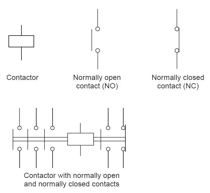
Electrical Symbols How to read electrical schematics? 3 CONTACTORS Wiring Diagram Symbol Contactor the contactor symbol in wiring diagrams is a standardized graphical representation that helps technicians and electricians easily. Contactors tend to be used for higher. a contactor schematic diagram, also known as a contactor wiring diagram or contactor ladder diagram, is a visual representation of the electrical connections. Find out the different symbols and components used in. this. Wiring Diagram Symbol Contactor.